d-wall

Top-Down vs Bottom-Up Construction with D-Walls: How Deep Urban Basements are Built

In densely populated metropolitan centers like Delhi-NCR, Mumbai, and Bengaluru, constructing multi-level basements presents significant engineering challenges. Tight property boundaries, adjoining heritage or high-rise structures, and congested access roads leave virtually no margin for ground settlement or structural deflection.

For developers, EPC contractors, and structural engineers, selecting the appropriate basement excavation methodology is a decisive factor in project timelines, budget control, and neighbor safety.

While conventional bottom-up construction remains standard for open plots, the top-down construction method utilizing permanent diaphragm walls (D-walls) has emerged as the definitive solution for deep basements (3 to 6 levels) in congested urban spaces.

Below is an engineering analysis of how top-down construction functions, how it contrasts with bottom-up methodology, and why diaphragm walls serve as the structural backbone of this modern approach.

What is Bottom-Up Construction?

In the traditional bottom-up sequence, the contractor first installs the perimeter deep excavation retaining wall (such as a diaphragm wall, secant pile wall, or soldier piles). The entire basement volume is then excavated down to the final formation level, supported by temporary multi-tier steel struts, rakers, or pre-stressed ground anchors.

Once bottom formation level is reached, the foundation raft slab is poured. The structure is then built upward floor-by-floor (B3, B2, B1, and Ground level). Construction of the revenue-generating superstructure above ground cannot begin until the basement roof slab is cast and cured.

What is Top-Down Construction?

In top-down construction, the permanent perimeter diaphragm wall and internal deep foundation piles (equipped with vertical steel plunge columns) are installed first. Next, the ground floor slab (Grade Slab) is cast directly over the ground, leaving predetermined openings for muck extraction.

From this point onward, construction proceeds in two opposite directions simultaneously:

  1. Upward: The superstructure frames (towers/commercial floors) begin rising immediately above the ground slab.

  2. Downward: Excavators work beneath the cast ground slab to dig out Basement 1, after which the B1 floor slab is cast. Excavation then continues downward to B2, B3, and ultimately the foundation raft.

In this sequence, each cast concrete floor slab serves as a rigid, permanent horizontal strut, eliminating the need for temporary steel propping.

2. Technical Step-by-Step Top-Down Execution Workflow

Executing a D-wall top down basement project requires exact geometric precision and stage-by-stage structural coordination:

Step 1: Perimeter Diaphragm Wall Installation

Specialized hydraulic grabs or trench cutters excavate deep trenches under stabilizing bentonite slurry to construct reinforced concrete D-wall panels (typically 600 mm to 1000 mm thick). This wall serves a dual role: an impermeable groundwater barrier during excavation and the permanent external basement wall for the structure.

Step 2: Bored Foundation Piles & Plunge Column Insertion

Internal bored cast-in-situ piles or barrettes are drilled down to load-bearing strata or rock. Before the pile concrete sets, heavy structural steel columns—known as plunge columns (built-up steel H-sections or concrete-filled tubes)—are lowered into the pile shafts. These plunge columns carry early superstructure loads while the basement levels beneath are still being excavated.

Step 3: Ground-Level Slab Construction (Stage 0)

The surface soil is leveled to the underside of the ground floor slab. A blinding concrete layer is poured directly on the ground, and the reinforced concrete ground floor slab is cast.

  • Crucial Detailing: Dedicated openings (typically 6 m x 4 m) are engineered into the slab to act as “muck-out openings” for hoisting excavated soil and lowering mini-excavators.

Step 4: Simultaneous Upward & Downward Construction

  • Superstructure Ascent: Tower cranes erected at ground level begin constructing superstructure columns and slabs (Floors 1, 2, 3, etc.).

  • Substructure Descent: Mini-excavators and skid-steer loaders operate beneath the ground slab, excavating earth down to the underside of the Basement 1 (B1) slab. The B1 floor is cast with rebar coupled to the D-wall perimeter and plunge columns.

Step 5: Repetition to Final Depth & Raft Placement

The excavation continues downward level-by-level (B2, B3) under the protection of the overhead cast slabs. Once the final basement level is reached, the primary foundation raft is cast, integrating the plunge columns, core walls, and the perimeter D-wall into a single monolithic foundation system.

3. Top-Down vs Bottom-Up: Engineering Comparison Matrix

Project Parameter Bottom-Up Construction Top-Down Construction Strategic Advantage
Project Schedule Sequential (Superstructure delayed until basements finish) Parallel (Superstructure & basements built simultaneously) Top-Down saves 4 to 8 months on multi-story towers.
Shoring System Requires multi-tier temporary steel struts or ground anchors Permanent RCC floor slabs act as horizontal diaphragm struts Top-Down eliminates temporary strut costs and site clutter.
Site Boundary Constraints Ground anchors require drilling into adjacent properties No encroachment; all structural loads remain within plot lines Top-Down avoids legal disputes with neighboring owners.
Lateral Wall Deflection Higher deflection risk during deep open excavation Extremely low deflection (stiff permanent slabs support wall) Top-Down provides maximum protection against settlement.
Groundwater Cutoff Often relies on secondary dewatering / sump pumping D-wall provides a watertight, seamless structural cut-off Top-Down is superior in high water-table zones.
Excavation Logistics Open-to-sky; standard large excavators used Underground mining conditions; requires mini-excavators and ventilation Bottom-Up is simpler for earth-moving contractors.
Engineering Complexity Standard civil engineering workflow Advanced geotechnical design, connection joints, plunge column tolerances Top-Down requires specialized contractors.

4. Why Diaphragm Walls are Mandatory for Top-Down Basements

While secant piles or sheet piles can be used for shallower basements, top-down construction for deep basements almost universally demands cast-in-situ diaphragm walls for three primary engineering reasons:

  1. Unmatched In-Plane and Out-of-Plane Rigidity:

    Because slabs are cast progressively downward, the perimeter wall must withstand massive lateral earth pressures with minimal displacement. The continuous structural stiffness of a 800 mm or 1000 mm thick reinforced concrete D-wall ensures that adjacent roads, buried utilities, and neighboring foundations experience negligible lateral movement.

  2. Watertight Perimeter Enclosure:

    D-walls installed with continuous waterstops (CWS joints) form an impermeable groundwater cut-off. In cities with high groundwater tables or coastal silts, this eliminates the risk of ground loss caused by soil piping and excessive dewatering.

  3. Permanent Load-Bearing Capacity:

    Unlike sheet piles or temporary shoring walls that are discarded or structurally decoupled, diaphragm walls are designed per IS 9556 and IS 456 to carry vertical axial loads transferred from edge basement slabs and perimeter columns.

For developers planning high-density urban projects, partnering with an experienced contractor for turnkey D-wall construction ensures that panel verticality (maintained within 1:200 tolerance) and plunge column alignment are executed without structural deviations.

5. Summary & Decision Matrix: When Should You Choose Top-Down?

Choose Top-Down Construction if your project matches these conditions:

  • Deep Basement Depth: The project involves 3 or more basement levels (>10–12 meters depth).

  • Critical Project Timeline: Early delivery of the superstructure is essential for commercial leasing or handover milestones.

  • Sensitive Urban Surroundings: The site is bordered by metro lines, heritage buildings, or major roadways where ground settlement must remain near zero.

  • Anchor Restrictions: Surrounding landowners, municipal authorities, or underground utility networks prohibit drilling soil nails or ground anchors beyond the site boundary.

Choose Bottom-Up Construction if:

  • The basement is relatively shallow (1 to 2 basements).

  • The site has wide boundaries allowing battered slopes or open excavation.

  • Capital expenditure limits upfront investment in specialized plunge columns and underground ventilation systems.

Frequently Asked Questions (FAQs)

1. How much time does top-down construction save compared to bottom-up?

Top-down construction typically reduces overall structural delivery timelines by 20% to 35% (saving 4 to 8 months) because the superstructure tower rises concurrently while the deep basements are being excavated and cast below.

2. What are plunge columns in top-down basement construction?

Plunge columns are heavy structural steel vertical sections (such as built-up H-beams or concrete-filled tubes) that are lowered into fresh bored pile concrete. They support the temporary and early-stage permanent vertical loads of the superstructure while basement floors below are being excavated.

3. Can top-down construction be done without diaphragm walls?

While contiguous or secant pile walls can occasionally be adapted for shallow top-down basements, deep basements (3+ levels) require diaphragm walls. D-walls deliver the structural stiffness, permanent vertical load capacity, and joint watertightness required for safe top-down engineering.

4. What are the ventilation and lighting challenges in top-down excavation?

Because earth excavation takes place underneath an enclosed concrete slab, contractors must install forced mechanical ventilation ducts, gas detection sensors (for carbon monoxide and methane), and industrial low-voltage lighting grids to ensure worker safety.

Read more...
Deep Soil Mixing

Deep Soil Mixing: Method, Process, Benefits, Equipment and Applications

Construction on weak, soft, or highly compressible soil can lead to excessive settlement, foundation instability, groundwater problems, and project delays. Deep Soil Mixing is an advanced ground improvement method used to enhance the engineering properties of such soil without completely excavating and replacing it.

The Deep Soil Mixing method mechanically blends existing soil with cementitious binders to create stronger and more stable soil columns, panels, or blocks below ground. It is widely used for foundation support, embankment stabilization, excavation support, groundwater control, and settlement reduction.

This guide explains the Deep Soil Mixing technique, its construction procedure, equipment, applications, advantages, and the differences between Wet and Dry Deep Soil Mixing.

What Is Deep Soil Mixing?

Deep Soil Mixing, also called DSM or the Deep Mixing Method, is an in-situ soil improvement process. “In situ” means that the soil is treated at its existing location instead of being removed from the site.

During the Deep Soil Mixing process, a specialised machine penetrates weak ground and blends it with binders such as cement, lime, or an engineered binder mixture. The binder reacts with the soil and water to form hardened soil-binder material with improved engineering properties.

Depending on the project requirements, the improved soil can be constructed as:

  • Individual soil-mixed columns
  • Overlapping columns
  • Continuous underground walls
  • Stabilised soil blocks
  • Panels or grids
  • Foundation-support zones

The resulting soil-binder elements can have greater strength, higher stiffness, lower compressibility, and reduced permeability compared with untreated soil.

How Does the Deep Soil Mixing Method Work?

The Deep Soil Mixing method uses mechanical mixing tools to break down the natural soil structure and distribute a controlled amount of binder throughout the treatment area.

A Deep Soil Mixing machine normally has one or more rotating shafts equipped with cutting blades, paddles, or augers. These mixing tools penetrate the ground to the required depth while binder is delivered through the equipment.

The binder may be introduced as a liquid slurry or dry powder. The selection depends on soil type, natural moisture content, groundwater conditions, required strength, environmental restrictions, and project specifications.

As the soil and binder are thoroughly mixed, they create a uniform soil-cement material. Once the material cures, it forms a stronger underground element capable of improving ground performance.

The final result depends on several factors, including:

  • Soil type and natural moisture
  • Binder composition and quantity
  • Mixing energy
  • Rotation and penetration speed
  • Treatment depth
  • Water-to-binder ratio
  • Quality of binder distribution
  • Curing conditions

Because these factors vary between sites, every Deep Soil Mixing project requires a site-specific design.

Step-by-Step Deep Soil Mixing Process

A properly planned Deep Soil Mixing procedure includes investigation, testing, construction, monitoring, and verification.

1. Geotechnical Site Investigation

The first step is to understand the ground conditions. Engineers conduct soil investigations to identify weak layers, soil composition, groundwater levels, obstructions, and the depth of treatment required.

The investigation may include boreholes, soil sampling, laboratory testing, Standard Penetration Tests, and Cone Penetration Tests. The collected information helps determine whether Deep Soil Mixing technology is suitable for the project.

2. Binder Selection and Mix Design

The contractor develops a suitable binder mix based on the soil characteristics and required performance. Common materials include cement, lime, and blended cementitious binders.

Laboratory trials may be conducted using different binder quantities. The treated samples are tested to evaluate strength, stiffness, workability, and permeability.

The objective is to select a mixture that meets the engineering requirements without using an unnecessary quantity of binder.

3. Field Trial Columns

Before full-scale production begins, trial columns may be installed at the site. These trials confirm whether the proposed Deep Soil Mixing technique, machinery, binder dosage, and installation parameters can achieve the required results.

Samples from the trial columns may be tested before approving the final construction methodology.

4. Equipment Positioning

The Deep Soil Mixing equipment is positioned at the designed column location. Correct alignment and verticality are important, particularly when overlapping columns are required to form a continuous wall or barrier.

5. Penetration and Binder Injection

The rotating mixing tool penetrates the soil to the specified depth. Binder is introduced during penetration, withdrawal, or both, depending on the selected system.

Machine parameters such as depth, rotation speed, binder flow, injection pressure, penetration rate, and withdrawal rate are monitored throughout the operation.

6. Soil and Binder Mixing

The cutting blades or augers mechanically mix the binder with the existing soil. Adequate mixing energy is required to produce consistent treated material and minimise untreated pockets.

When the tool reaches the required depth, additional mixing may be carried out before it is withdrawn.

7. Formation and Curing

The completed process leaves a soil-mixed column in the ground. Multiple columns can be arranged or overlapped to create walls, panels, grids, or stabilised blocks.

The treated material gradually gains strength as the binder reacts with the soil and water. Curing time depends on binder type, soil chemistry, moisture, temperature, and project specifications.

8. Quality Control

Quality control verifies that the completed work meets the approved design. It may include:

  • Installation parameter records
  • Binder-consumption monitoring
  • Depth and verticality checks
  • Wet grab sampling
  • Core sampling
  • Strength testing
  • Permeability testing
  • Column continuity assessment

Accurate digital records provide traceability for every installed column.

Wet Deep Soil Mixing

Wet Deep Soil Mixing uses a binder mixed with water to form a pumpable slurry. The slurry is delivered through the mixing shaft and blended with the soil using rotating tools.

This method can be used for many types of treatable soil and is commonly selected where accurate slurry delivery and thorough binder distribution are required.

Typical applications include:

  • Foundation support
  • Retaining walls
  • Excavation support
  • Groundwater barriers
  • Embankment stabilization
  • Marine construction
  • Liquefaction mitigation

During Wet Deep Soil Mixing, the contractor must control the slurry density, water-to-binder ratio, injection rate, pressure, and total binder quantity. These factors influence the consistency and final strength of the treated soil.

Dry Deep Soil Mixing

Dry Deep Soil Mixing introduces powdered binder directly into the ground using compressed air. The binder reacts with moisture already present in the soil.

The method is generally suitable for soft, wet, and moisture-rich soils. Because additional water is not used to prepare a slurry, Dry Deep Soil Mixing may produce less wet spoil in suitable ground conditions.

However, its effectiveness depends on natural soil moisture, binder distribution, air pressure, soil chemistry, and mixing quality. Dust management and environmental controls may also be necessary.

Wet vs Dry Deep Soil Mixing

Feature Wet Deep Soil Mixing Dry Deep Soil Mixing
Binder form Liquid slurry Dry powder
Water requirement Water is added Uses natural soil moisture
Delivery system Pump and injection lines Compressed-air system
Typical suitability Broad range of treatable soils Soft, high-moisture soils
Important controls Slurry ratio, pressure and flow Moisture, air pressure and dosage
Spoil condition May generate wet spoil May reduce wet spoil

The best method should be selected after examining the site conditions and required engineering performance. Neither option is automatically suitable for every project.

Major Applications of Deep Soil Mixing

Foundation Support

Deep-mixed columns can improve weak ground below buildings, industrial plants, tanks, bridges, and other structures. The strengthened soil helps distribute structural loads and improve foundation performance.

Settlement Reduction

Soft soil can compress when subjected to new loads. Deep Soil Mixing increases the stiffness of the treated ground and helps control total and differential settlement.

Embankment Stabilization

The technique can support highway, railway, approach, and flood-protection embankments constructed over weak soil.

Excavation Support

Overlapping columns can form soil-mixed retaining walls around deep excavations. Structural reinforcement may be inserted where required by the engineering design.

Groundwater Control

Continuous soil-mixed panels can create low-permeability barriers that help reduce groundwater movement and seepage into excavations.

Slope Stabilization

Deep-mixed elements can improve the shear strength of weak soil and provide additional resistance along potential slope failure zones.

Liquefaction Mitigation

Deep Soil Mixing technology may be used to increase ground stiffness and reduce deformation in liquefaction-sensitive areas. The treatment pattern must be designed according to site-specific seismic conditions.

Deep Soil Mixing Benefits

Important Deep Soil Mixing benefits include:

  • Increased soil strength and stiffness
  • Improved foundation bearing performance
  • Reduced total and differential settlement
  • Treatment of soil at substantial depths
  • Reduced need for soil excavation
  • Lower demand for imported replacement material
  • Flexible column and wall arrangements
  • Improved slope and embankment stability
  • Potential groundwater and seepage control
  • Reduced vibration compared with some driven systems

One of the most valuable advantages of Deep Soil Mixing is its ability to improve existing ground in place. This can reduce excavation, material transportation, disposal requirements, and disruption around the project site.

The benefits achieved depend on design quality, ground conditions, construction control, and testing.

Deep Soil Mixing Equipment

Specialised Deep Soil Mixing equipment is necessary to achieve the required depth, diameter, mixing quality, and production rate.

A typical setup may include:

  • Crawler-mounted drilling rig
  • Single or multiple mixing shafts
  • Cutting blades, paddles, or augers
  • Cement or binder storage silos
  • Slurry batching plant
  • Injection pumps
  • Air compressors
  • Binder delivery lines
  • Flow and pressure sensors
  • Depth and verticality monitoring systems
  • Digital data-recording technology

The Deep Soil Mixing machine should be selected according to soil resistance, treatment depth, column size, available working space, headroom, and project-access conditions.

Choosing a Deep Soil Mixing Contractor

Deep Soil Mixing is a specialist operation that requires geotechnical understanding, appropriate machinery, trained operators, and strict quality control.

When selecting a Deep Soil Mixing contractor, consider:

  • Experience with similar ground conditions
  • Knowledge of wet and dry mixing methods
  • Availability of suitable equipment
  • Trial-mixing capabilities
  • Real-time construction monitoring
  • Testing and quality-control procedures
  • Health and safety planning
  • Environmental management
  • Technical documentation and reporting

A professional Deep Soil Mixing company should review the site investigation, structural loads, groundwater conditions, treatment depth, and performance criteria before recommending a solution.

Conclusion

Deep Soil Mixing is an effective ground improvement technique for strengthening weak soil, reducing settlement, supporting foundations, stabilising embankments, retaining excavations, and controlling groundwater movement.

Both Wet Deep Soil Mixing and Dry Deep Soil Mixing can produce strong soil-binder elements, but the appropriate method depends on the project’s ground conditions and engineering requirements.

Successful implementation requires proper investigation, binder testing, suitable Deep Soil Mixing equipment, controlled construction, and reliable quality verification.

For professional Deep Soil Mixing services, contact Grimtech. Our team can assess your project requirements and recommend an appropriate ground improvement solution for safe and efficient construction.

Read more...
D-Wall Construction Process

D-Wall Construction Process: 10 Essential Steps from Guide Wall to Final Excavation

A diaphragm wall—commonly called a D-wall—is a reinforced-concrete wall constructed below ground before the main excavation begins. It can retain soil, control groundwater and, when designed for the purpose, form part of the permanent basement or underground structure. D-walls are widely considered for metro works, deep basements, shafts, underpasses, waterfront structures and other projects where excavation depth, restricted space or nearby assets make ground movement a serious concern.

Successful D-wall execution depends on much more than excavating a trench and filling it with concrete. Soil conditions, groundwater, panel sequencing, slurry properties, verticality, reinforcement handling, joint treatment and concreting continuity all affect the final result. This guide explains the typical construction sequence and the quality controls that project teams should plan from the beginning.

What Is D-Wall Construction?

D-wall construction is a panel-by-panel method of creating a continuous underground reinforced-concrete wall. A narrow trench is excavated to the designed depth while bentonite or an approved polymer slurry supports the exposed soil faces. After the trench is cleaned and checked, a prefabricated reinforcement cage is lowered into the panel. Concrete is then placed from the bottom upward through tremie pipes, displacing the supporting slurry for treatment and reuse or disposal as specified.

Individual primary and secondary panels are connected through designed joints to create a continuous wall. Depending on the structural design, the completed wall may provide temporary excavation support, permanent earth retention, groundwater cut-off, foundation resistance, or a combination of these functions.

When Is a Diaphragm Wall Considered?

The system is usually evaluated when the project requires deep excavation with strict control of soil movement and water ingress. Common use cases include:

Multi-level basements in congested urban locations

Underground metro stations, access shafts and tunnel portals

Cut-and-cover underpasses and transportation structures

Marine, port and waterfront developments

Deep excavation close to existing buildings or utilities

Cut-off walls for dams, reservoirs and water-retaining works

The final retaining system should always be selected using project-specific geotechnical information, structural loads, groundwater conditions, constructability, environmental constraints and commercial evaluation.

The D-Wall Construction Process

1. Site investigation and design planning: The process starts with geotechnical investigation, groundwater assessment, utility mapping and a survey of adjacent structures. Engineers use this information to define the wall alignment, panel sequence, design depth, thickness, reinforcement, joint system, excavation support and monitoring plan. Access, crane standing areas, slurry circulation routes and spoil handling should also be planned before mobilisation.

2. Working platform and site preparation: A stable, level working platform is prepared for cranes, grabs, slurry equipment and service vehicles. The platform must support the intended plant under operating conditions. Survey control points, exclusion zones, drainage, lighting and safe access are established. Slurry tanks, mixing units, desanders and testing facilities are positioned to maintain an orderly circulation system.

3. Guide-wall construction: Two shallow, parallel reinforced-concrete guide walls are built along the D-wall alignment. They guide the excavation equipment, define wall position and panel width, support the trench opening and provide a reference for verticality and reinforcement placement. Accurate survey setting-out at this stage is essential because an alignment error can continue through the full panel depth.

4. Panel layout and excavation sequence: The wall is divided into panels according to the design and available equipment. The sequence is planned so that adjacent panels can be constructed without damaging fresh concrete or compromising joint continuity. Panel excavation normally follows a controlled bite sequence using a hydraulic grab; a trench cutter or hydromill may be selected where ground conditions and project specifications require it.

5. Slurry-supported trench excavation: As soil is removed, supporting slurry is maintained at the specified level to provide pressure against the trench faces. The excavation proceeds in controlled stages while depth, alignment and verticality are monitored. The team must manage slurry loss, groundwater changes, obstructions and variations in soil or rock without leaving the trench unsupported.

6. Trench cleaning and verification: After reaching the required depth, loose material and sediment are removed from the panel base. Slurry is circulated or treated until its properties meet the project specification for reinforcement placement and concreting. The team verifies panel depth, width, alignment, verticality, base cleanliness and slurry parameters. Nonconforming conditions should be corrected before the cage is lowered.

7. Joint or stop-end installation: The selected stop-end, joint former or water-bar system is installed as required by the panel design. Joints influence structural continuity and water tightness, so their position, cleanliness, profile and removal sequence require close control. Joint preparation must follow the approved method statement and designer’s requirements.

8. Reinforcement-cage fabrication and lowering: The wall-panel cage is fabricated to approved drawings with the required bars, spacers, couplers, lifting points, embedded items and concrete cover provisions. Lifting is planned to avoid excessive cage distortion. The crane lowers the cage slowly into the slurry-filled trench while the team checks orientation, level, clearance and stability. Long cages may be handled in sections using approved connection details.

9. Tremie concreting: Concrete is placed continuously from the bottom of the panel using tremie pipes. The tremie outlet remains embedded in fresh concrete by the amount required in the approved procedure, helping prevent slurry contamination and segregation. As the concrete level rises, slurry is displaced, collected and treated. Concrete volume, delivery continuity, level rise and theoretical-versus-actual consumption are recorded throughout the pour.

10. Panel completion and subsequent excavation: After concrete gains the specified strength, the adjoining panel sequence continues until the wall is complete. During bulk excavation, capping beams, struts, anchors, slabs or other supports are installed in the designed sequence. The exposed wall is inspected for joints, seepage, surface defects and alignment. Instrumentation and movement monitoring continue wherever specified.

Key Equipment Used in D-Wall Construction

Hydraulic clamshell grab for panel excavation

Trench cutter or hydromill where specified

Crawler crane for excavation tools and reinforcement cages

Bentonite or polymer mixing, storage and circulation system

Desanding and slurry-treatment equipment

Tremie pipes and concrete-delivery equipment

Depth, alignment and verticality monitoring instruments

Pumps, generators and approved spoil-handling equipment

Critical Quality-Control Checks

Quality assurance should follow the approved inspection and test plan, project specifications and applicable standards. Important controls commonly include:

Survey verification of alignment, guide walls and panel coordinates

Working-platform certification and equipment inspection

Slurry density, viscosity, sand content, pH and fluid-loss testing as specified

Panel depth, geometry and verticality records

Base-cleanliness and sediment checks before concreting

Reinforcement-cage dimensions, cover, lifting points and embedded items

Concrete workability, sampling, volume and continuous-pour records

Tremie position and embedment monitoring

Joint condition, seepage inspection and wall movement monitoring

Common D-Wall Execution Risks

Trench instability

Insufficient slurry head, unsuitable slurry properties, uncontrolled groundwater or prolonged open-trench time can increase instability risk. Continuous monitoring and an approved contingency plan are essential.

Excessive verticality deviation

Inaccurate guide walls, equipment misalignment, obstructions and variable strata can affect panel geometry. Early measurement allows corrective action before the deviation becomes critical.

Contaminated concrete or inclusions

Interrupted concreting, poor base cleaning or incorrect tremie operation can allow slurry or sediment to enter the concrete. A continuous supply plan, clean trench and controlled tremie procedure help reduce this risk.

Joint leakage

Poorly formed, displaced or contaminated joints may create seepage paths. Correct joint-system selection, installation, cleaning and inspection are central to water-control performance.

Reinforcement-cage handling problems

Large wall-panel cages can distort or become difficult to lower if lifting points, stiffness, clearances or splice details are not properly planned. A documented lifting study and trial checks can prevent delays.

D-Wall Construction for Different Projects

Deep basements

The wall can retain surrounding soil and groundwater while excavation proceeds within a restricted property boundary. When designed as a permanent wall, it may also become part of the basement enclosure.

Metro stations and shafts

D-walls can provide stiff perimeter support for deep cut-and-cover structures where nearby buildings, roads and utilities require careful movement control.

Waterfront and cut-off applications

A properly designed continuous wall can help reduce subsurface seepage and provide retention in challenging groundwater environments. Joint detailing and construction quality are particularly important in these applications.

Why Experienced Planning and Execution Matter

A D-wall is built largely below ground, so many critical conditions cannot be inspected visually after concreting. The project therefore depends on disciplined planning, suitable equipment, trained personnel, real-time records and timely engineering decisions. Contractor evaluation should consider relevant project experience, proposed equipment, technical team, quality-control system, safety planning, resource availability and the ability to respond to unexpected ground conditions—not only the quoted rate.

Plan Your D-Wall Project with Grimtech

Every diaphragm-wall project has a different combination of depth, soil, groundwater, access, structural and scheduling requirements. Grimtech provides ground-engineering and deep-foundation solutions for infrastructure and construction projects across India. Share your geotechnical report, drawings, site location, anticipated wall dimensions and project programme so the technical team can review the execution requirement.

Explore Grimtech’s D-wall construction services:

Frequently Asked Questions

What is the D-wall construction process?

It is a panel-by-panel underground wall-construction method involving guide walls, slurry-supported excavation, trench cleaning, joint preparation, reinforcement-cage lowering and continuous tremie concreting.

Why is bentonite slurry used during excavation?

The slurry provides supporting pressure against exposed trench faces, carries suspended particles and helps keep the excavation stable until concrete placement. Its properties must be tested and controlled according to the project specification.

What is the purpose of a guide wall?

Guide walls establish the alignment and panel position, guide excavation equipment and support the upper part of the trench.

How is concrete placed in a diaphragm-wall panel?

Concrete is generally placed from the bottom upward through tremie pipes. The operation is kept continuous and controlled so the rising concrete displaces slurry while limiting contamination and segregation.

Can a D-wall become part of the permanent structure?

Yes, when it is designed accordingly, a diaphragm wall may serve as the permanent retaining or basement wall in addition to supporting excavation.

What information is needed for a D-wall quotation?

Useful inputs include site location, geotechnical report, drawings, wall length, depth and thickness, reinforcement details, access constraints, groundwater information, programme and scope responsibilities.

How is D-wall quality checked?

Checks commonly cover survey alignment, slurry properties, trench depth and verticality, base cleanliness, cage inspection, concrete quality and volume, tremie records, joints, seepage and structural monitoring.

What causes leakage through a diaphragm wall?

Potential causes include joint defects, concrete contamination, inclusions, cracking or unsuitable detailing. The actual cause should be investigated before selecting a remedial method.

Read more...
Sheet Pile Installation

Sheet Pile Installation: Complete Guide, Process & Cost in India

Introduction

Sheet pile installation is one of the most dependable creation strategies used for soil retention, excavation support, and waterfront systems. Whether you’re working on basements, bridges, or marine production, sheet piling affords strength, sturdiness, and price performance.

In this guide, you’ll examine the entirety about sheet piling—from set up strategies to a detailed price breakdown—helping you are making the right choice for your venture.

What is Sheet Pile Installation?

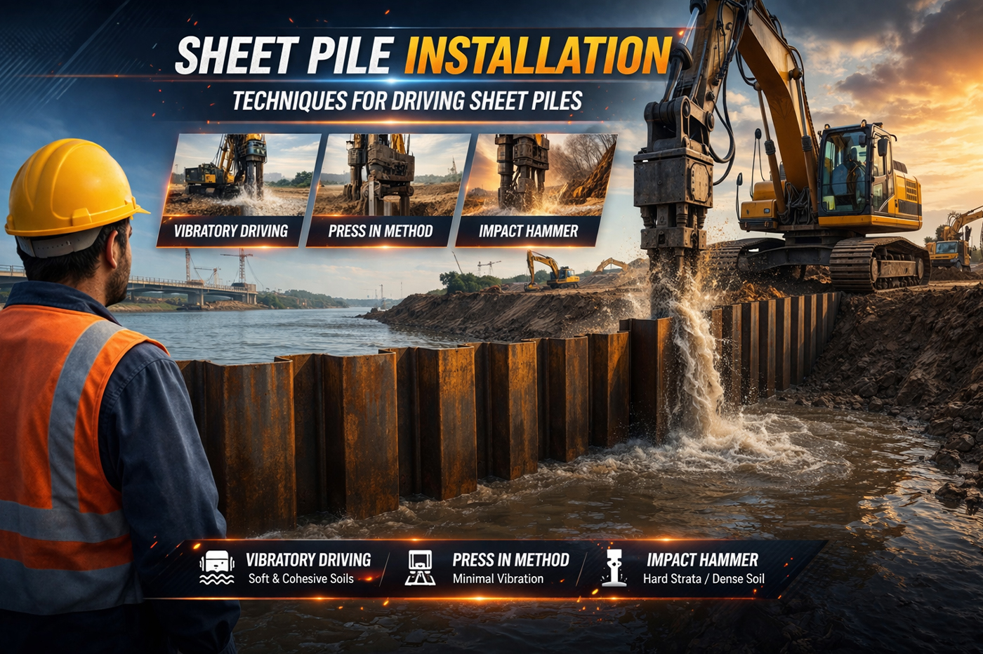
Sheet pile set up is a method wherein interlocking metal sheets are driven into the ground to shape a non-stop wall. These walls are broadly used for:

  • Retaining walls
  • Flood protection
  • Basement creation
  • Marine systems
  • Excavation help

Steel sheet piles are favored due to the fact they offer high power, reusability, and quicker installation compared to standard concrete structures.

Types of Sheet Pile Installation Methods

1. Vibratory Hammer Installation

This is the maximum common method wherein a vibratory hammer is used to pressure piles into the floor. It is speedy and fee-effective.

2. Impact Hammer Installation

Used for difficult soil conditions, this approach presents deeper penetration however is slightly extra high-priced.

three. Press-in Method

A noise-free and vibration-free technique, perfect for city regions in which minimum disturbance is required.

Sheet Pile Installation Cost in India

The value of sheet piling relies upon on more than one factors such as soil circumstance, task length, and material first-rate.

🔹 Average Cost Overview

  • Steel sheet piling cost in keeping with meter: ₹three,000 – ₹10,000
  • Sheet pile set up fee consistent with foot: ₹1,000 – ₹three,000
  • Sheet piling fee per ton: ₹70,000 – ₹1,20,000
  • Sheet piling price in keeping with rectangular meter: ₹2,500 – ₹eight,000

If you are trying to find steel sheet pile installation price in India, those tiers can range relying on area and contractor information.

Steel Sheet Pile Wall Cost Breakdown

Understanding the metal sheet pile wall production cost breakdown allows in better budgeting:

1. Material Cost

Includes steel great, thickness, and form of sheet pile.

2. Installation Charges

Labor, machinery, and operational fees contribute substantially.

3. Transportation Cost

Depends on site area and logistics.

4. Equipment Cost

Use of cranes, vibratory hammers, or hydraulic press machines.

5. Site Conditions

Hard soil or waterlogged areas increase fees.

Cost of Sheet Piling for Retaining Wall

The fee of sheet piling for preserving wall initiatives usually stages between ₹four,000 to ₹12,000 per meter depending on intensity and load requirements.

Steel sheet piles are regularly more low-priced than concrete partitions because of:

  • Faster set up
  • Reduced exertions
  • Long-time period sturdiness

Steel Sheet Pile Installation Cost Per Meter in India

When calculating steel sheet pile set up fee in line with meter in India, consider:

  • Soil type (smooth, sandy, rocky)
  • Depth of set up
  • Equipment used
  • Project size

For bulk initiatives, contractors regularly offer a sheet piling contractors fee estimate, that could extensively lessen according to-unit pricing.

How to Get the Best Price for Sheet Pile Installation

To get the first-rate rate for sheet pile installation, comply with those pointers:

  • Compare more than one contractor quotations
  • Choose experienced sheet piling contractors
  • Opt for bulk set up to reduce cost
  • Check if the contractor gives both metallic sheet pile supplier and set up price in one bundle

Searching for metallic sheet pile set up price near me also can assist you discover local contractors presenting competitive costs.

Factors Affecting Sheet Pile Installation Cost

Several factors have an impact on pricing:

  • Soil situation
  • Depth and duration of piles
  • Type of metallic used
  • Equipment and era
  • Project area

A right sheet piling contractors fee estimate must continually encompass a lot of these elements.

Advantages of Steel Sheet Piling

  • High electricity and sturdiness
  • Reusable and green
  • Faster installation
  • Cost-effective compared to concrete
  • Suitable for temporary and permanent structures

Conclusion

Sheet pile installation is a clever and green solution for current production wishes. Whether you’re making plans a preserving wall or a massive infrastructure mission, knowledge the cost, techniques, and advantages allow you to make better selections.

If you’re making plans a mission, always seek advice from professionals and request a detailed estimate to get the maximum accurate pricing and ensure lengthy-term overall performance.

FAQs

Q1. What is the average sheet piling fee in India?

The cost varies from ₹three,000 to ₹10,000 in step with meter relying on undertaking requirements.

Q2. Is sheet piling inexpensive than concrete keeping partitions?

Yes, in lots of cases sheet piling is greater cost-effective because of quicker set up and lower labor fees.

Q3. How do I find sheet piling contractors near me?

Search domestically and examine rates to discover the high-quality contractor presenting aggressive pricing and quality service.

Read more...
ground development

Ground Improvement: Techniques, Methods & Modern Solutions in Construction

Ground improvement is a essential technique in modern creation that guarantees soil is robust sufficient to support systems competently and correctly. Whether it’s highways, bridges, excessive-rise homes, or commercial initiatives, ground development strategies play a key position in enhancing soil homes and stopping structural failures.

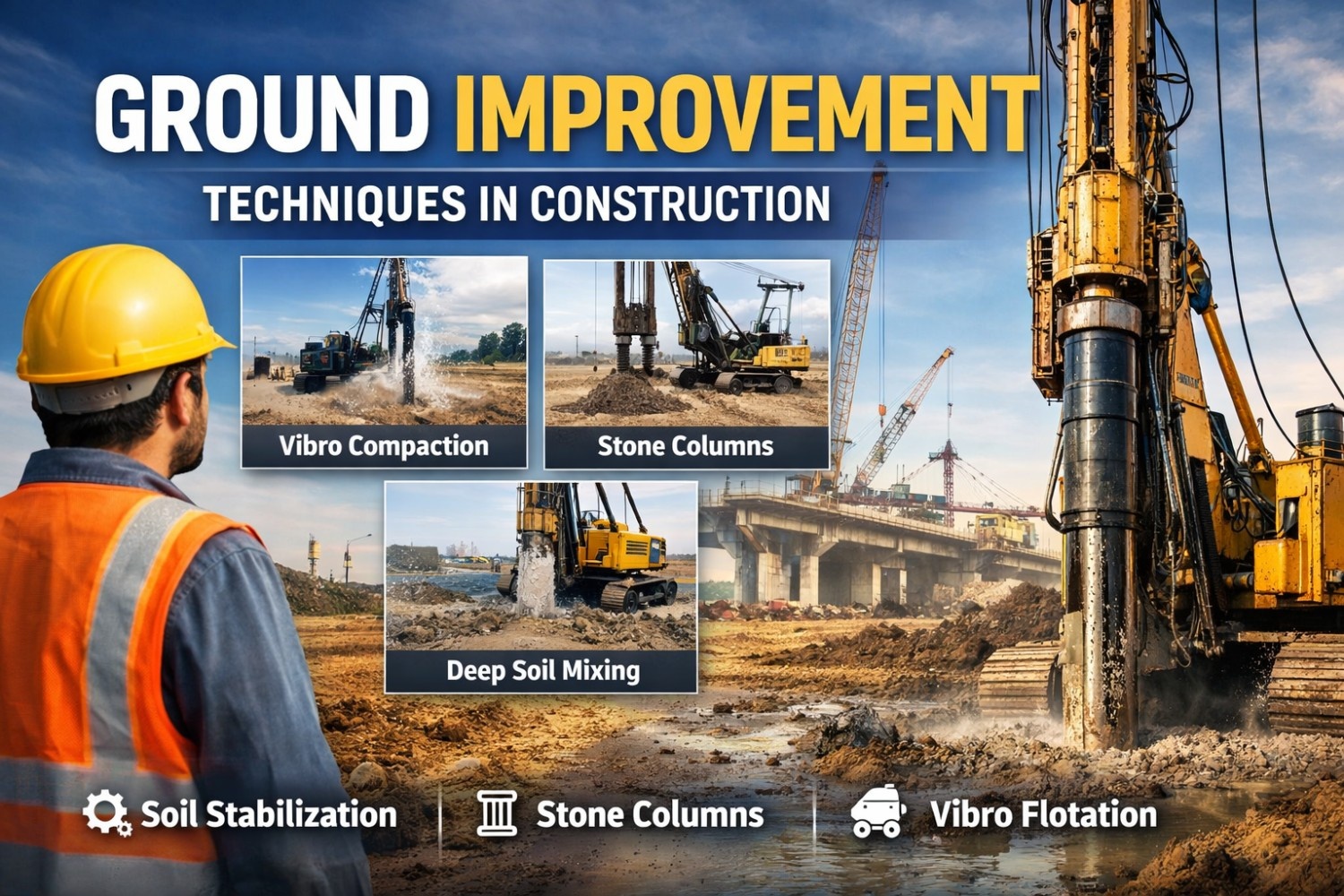
In this comprehensive guide, we’ll explore soil improvement techniques, including Deep Soil Mixing, vibro compaction, stone columns, and other advanced ground stabilization methods used in modern construction.

What is Ground Improvement?

Ground development refers to a number of strategies used to enhance the engineering residences of soil. These techniques increase soil power, lessen agreement, and enhance load-bearing ability, making the floor appropriate for production.

It is extensively utilized in:

  • Weak or gentle soil regions
  • Coastal and reclaimed land
  • Infrastructure and industrial projects

 Importance of Ground Improvement in Construction

Using proper floor improvement in construction offers several advantages:

✔ Improves soil energy and balance

✔ Reduces agreement and deformation

✔ Enhances load-bearing ability

✔ Minimizes construction risks

✔ Increases lifespan of systems

This is why civil engineering floor improvement has become vital in cutting-edge infrastructure improvement.

 Types of Ground Improvement Techniques

There are several soil stabilization strategies used depending on soil situations and project requirements:

1. Vibro Compaction Method

The vibro compaction method is used to densify loose granular soils like sand. A vibrating probe is inserted into the floor, rearranging soil particles into a denser configuration.

Key Benefits:

  • Increases soil density
  • Reduces agreement
  • Ideal for sandy soils

2. Vibro Flotation Technique

The vibro flotation method (also called vibroflotation) is a famous ground stabilization method used for deep soil improvement.

Applications:

  • Land reclamation projects
  • Ports and harbors
  • Large infrastructure developments

3. Stone Column Installation

Stone column installation involves putting columns of crushed stone into smooth soil to enhance strength and drainage.

Advantages:

  • Improves load-bearing capacity
  • Reduces liquefaction risk
  • Enhances drainage

4. Soil Stabilization Techniques

Various soil stabilization strategies are used to regulate soil homes:

  • Mechanical stabilization (compaction)
  • Chemical stabilization (lime, cement)
  • Geosynthetics reinforcement
  • Thermal stabilization

These methods are broadly utilized in infrastructure soil stabilization tasks inclusive of roads, railways, and airports.

5. Deep Soil Mixing

Deep Soil Mixing (DSM) is an advanced ground improvement technique used to improve the strength and stability of weak or soft soils. In this method, in-situ soil is mechanically mixed with binding agents such as cement or lime to form stronger soil-cement columns or panels.

The deep soil mixing method is particularly useful where conventional foundation solutions may not be suitable. It can improve soil bearing capacity, reduce settlement, and increase overall ground stability.

Applications of Deep Soil Mixing:

  • Soft and weak soil stabilization
  • Foundation ground improvement
  • Infrastructure and industrial projects
  • Embankments and retaining structures
  • Settlement reduction

For projects requiring advanced ground improvement solutions, Deep Soil Mixing can be selected based on soil conditions, required strength, groundwater conditions, and project requirements.

6. Dynamic Compaction

Heavy weights are dropped from heights to compact unfastened soil layers, making it suitable for construction.

 Applications of Ground Improvement

Ground improvement is vital in various sectors:

  • Residential & commercial creation
  • Highways and railways
  • Airports and ports
  • Industrial vegetation
  • Urban infrastructure initiatives

These programs highlight the importance of infrastructure soil stabilization in large-scale developments.

 Choosing the Right Ground Improvement Method

Selecting the fine floor stabilization technique depends on:

  • Soil kind and circumstance
  • Project length and cargo requirements
  • Budget and timeline
  • Environmental elements

A right geotechnical investigation is continually recommended before choosing a technique.

 Future of Ground Improvement in India

With fast urbanization and infrastructure boom, call for for floor development strategies is increasing in India. Advanced technologies like vibro techniques, geosynthetics, and green stabilization answers are shaping the destiny of the industry.

 Conclusion

Ground development is a essential part of modern creation that ensures safety, durability, and efficiency. From vibro compaction approach to stone column set up, these superior soil development strategies assist engineers triumph over difficult ground conditions.

Read more...
Impact hammer in india

Impact Hammer in India: Complete Guide for Construction & Pile Driving

The demand for robust and dependable foundation device is rapidly increasing within the Indian creation region. One of the most vital equipment utilized in contemporary piling and basis work is the Impact Hammer. Whether it is used for riding piles, heavy-duty creation paintings, or commercial applications, the Impact Hammer in India plays a essential function in ensuring structural stability.

In this detailed guide, we will explore what an impact hammer is, the way it works, its packages, sorts, and why it’s far extensively used in infrastructure and basis initiatives throughout India.

What is an Impact Hammer?

An impact hammer is a effective creation tool designed to deliver excessive-electricity blows to pressure piles deep into the ground or destroy difficult surfaces. It is normally used in piling operations in which steel, concrete, or wooden piles want to be embedded into soil or rock to assist heavy systems.

Modern effect hammer machines are engineered with advanced hydraulic structures that offer unique and regular placing pressure, making them ideal for big-scale production projects.

Importance of Impact Hammer in India’s Construction Industry

India is witnessing speedy growth in infrastructure development, together with highways, metro tasks, bridges, and high-upward push homes. These initiatives require strong foundation systems.

A production effect hammer in India is broadly used as it helps:

  • Drive piles efficaciously into tough soil layers
  • Increase creation pace
  • Improve basis power
  • Reduce guide labor
  • Ensure structural stability for heavy structures

From metro rail tasks to marine creation, effect hammer equipment has grow to be critical in present day civil engineering.

Types of Impact Hammer Used in India

Different production projects require specific varieties of hammers depending on soil conditions, pile type, and venture scale.

1. Hydraulic Impact Hammer

A hydraulic impact hammer is one of the most superior piling equipment used in creation. It operates the use of hydraulic strain to generate effective blows.

Benefits:

  • High strength performance
  • Reduced noise and vibration
  • Precise manage of impact force
  • Suitable for massive infrastructure tasks

Hydraulic hammers are extensively utilized in bridge production, offshore piling, and metro rail tasks.

2. Pile Driving Impact Hammer

A pile driving impact hammer is mainly designed to install piles into the ground to assist heavy masses.

These hammers are used for:

  • Steel pile installation
  • Concrete pile riding
  • Marine foundation projects
  • Bridge and toll road production

The impact hammer for pile riding guarantees that piles reach the required depth and load-bearing capability.

3. Heavy Duty Impact Hammer

A heavy obligation effect hammer is utilized in tasks in which high strength output is required to force piles into dense soil or rocky floor.

Common programs include:

  • Deep basis production
  • Industrial infrastructure initiatives
  • Port and dockyard creation

These hammers are designed to withstand non-stop heavy-responsibility operations in traumatic environments.

4. Industrial Impact Hammer Machine

An commercial effect hammer system is used no longer simplest in construction but additionally in engineering trying out and structural analysis.

Industries that normally use these machines consist of:

  • Construction companies
  • Civil engineering laboratories
  • Infrastructure improvement companies

These machines supply steady force and reliable performance in diverse business applications.

Applications of Impact Hammer in India

The Impact Hammer in India is used throughout multiple sectors of the development and engineering industries.

1. Pile Foundation Construction

Impact hammers are important for installing piles that help homes, bridges, and business systems.

2. Bridge and Highway Projects

Large infrastructure initiatives require strong foundations, making impact hammer gadget a key device for pile installation.

3. Marine Construction

Ports, docks, and offshore systems require piles pushed deep into seabeds the usage of hydraulic effect hammers.

4. Metro and Railway Projects

Urban infrastructure initiatives depend heavily on pile using effect hammers to aid improved tracks and stations.

5. Industrial Infrastructure

Factories, strength flowers, and warehouses require strong foundations constructed the use of heavy obligation effect hammer era.

Advantages of Using Impact Hammer Equipment

Construction corporations in India choose present day effect hammer machines because they provide multiple advantages.

High Efficiency

Impact hammers deliver powerful blows that quick power piles into the floor, reducing venture time.

Strong Foundation Support

They make certain deep pile penetration, which improves structural balance.

Cost-Effective Solution

Using advanced construction effect hammer device in India reduces exertions charges and mission delays.

Suitable for Different Soil Conditions

Impact hammers can work efficaciously in clay, sand, and even rocky terrain.

Factors to Consider Before Choosing an Impact Hammer

Before choosing an commercial impact hammer machine, it’s far critical to recollect numerous elements:

  • Pile kind – steel, concrete, or wooden
  • Soil condition – soft soil or rock layers
  • Project size – small production or big infrastructure
  • Hammer strength capability – required placing pressure
  • Equipment compatibility – with cranes or rigs

Choosing the right impact hammer for pile riding ensures higher performance and assignment performance.

Future of Impact Hammer Technology in India

With fast infrastructure growth and government funding in highways, clever towns, and metro rail tasks, the call for for superior hydraulic impact hammers is anticipated to boom substantially.

Modern manufacturers are specializing in:

  • Energy-green designs
  • Low-noise effect hammers
  • Smart monitoring systems
  • High-performance piling gadget

These improvements will in addition enhance the efficiency and reliability of effect hammer device used in Indian production initiatives.

Conclusion

The Impact Hammer in India is an crucial piece of system for current creation and basis engineering. From using piles for bridges to assisting high-upward thrust homes, impact hammers provide the energy and precision needed for strong structural foundations.

Whether it is a hydraulic effect hammer, pile driving effect hammer, or heavy duty effect hammer, those machines play a essential function in making sure the achievement of huge infrastructure and industrial initiatives.

As India maintains to extend its infrastructure, the usage of advanced business impact hammer machines will stay a key factor of secure, green, and sturdy construction practices.

Vibro Hammer: Modern Solution for Efficient Pile Driving

A vibro hammer is another advanced equipment widely used in foundation and piling work. Unlike an impact hammer that uses repeated ضرب (blows), a vibro hammer works on the principle of vibration to drive piles into the ground.

This machine generates high-frequency vibrations that reduce soil resistance, allowing piles to penetrate smoothly and efficiently. Vibro hammers are especially useful in sandy and loose soil conditions where traditional impact hammer machines may be less efficient.

Key Benefits of Vibro Hammer

  • Faster pile installation compared to traditional methods

  • Reduced noise and vibration impact on surroundings

  • Ideal for sheet piles and steel piles

  • Energy-efficient and cost-effective

Applications of Vibro Hammer

  • Sheet pile installation

  • Marine and waterfront construction

  • Temporary and permanent retaining structures

  • Bridge and metro projects

In modern construction projects across India, both hydraulic impact hammer and vibro hammer are used depending on soil type and project requirements. While impact hammer for pile driving is suitable for hard soil and deep foundations, vibro hammers are preferred for quicker and smoother pile installation in softer ground conditions.

Read more...
vibro float in india

Vibro Float in India: Complete Guide to Vibro Float Construction & Ground Improvement

The Vibro Float in India method is turning into one of the most effective solutions for floor improvement and soil stabilization in contemporary production tasks. With rapid city improvement, infrastructure projects together with bridges, ports, highways, and business homes require sturdy and solid foundations.

The vibro flotation approach allows engineers enhance weak soil situations via densifying unfastened soil and increasing its load-bearing ability. This method is widely used in projects where conventional foundation methods are not powerful.

In this manual, we can provide an explanation for vibro float production in India, how the vibro compaction approach works, styles of vibroflot device, and its benefits in ground improvement tasks.

What is Vibro Float?

A vibro glide is a specialised vibroflot machine used for soil densification through vibration and water jetting. The device penetrates loose soil layers and compacts them, making the ground stable for construction.

The vibro glide ground improvement method is normally utilized in sandy and granular soils wherein traditional compaction methods are tough to use.

Key Features

  • Improves soil density
  • Reduces settlement risk
  • Increases load-bearing ability
  • Suitable for large infrastructure initiatives

Because of these advantages, vibro flow production in India is more and more used in metro, dual carriageway, and business developments.

Vibro Flotation Technique Explained

The vibro flotation approach works by means of putting a vibrating probe (vibroflot) into the floor. The vibration rearranges soil debris and fills voids, growing a denser soil structure.

Working Process

  1. Insertion of Vibroflot
  2. The vibroflot gadget penetrates the soil using vibration and water strain.
  3. Soil Densification
  4. Vibration rearranges loose soil debris, lowering air gaps.
  5. Backfilling Material
  6. Sand or gravel is introduced to boom balance.
  7. Compaction
  8. The soil becomes dense and strong enough to assist heavy structures.

This vibro compaction approach is widely used in regions with loose sand deposits.

Vibro Float Construction in India

Vibro waft production in India is extensively applied in large-scale infrastructure tasks. Many production businesses use this technology to improve soil conditions before foundation paintings starts.

Common Applications

  • Highway and bridge production
  • Ports and marine systems
  • Industrial plants
  • Airports and railway infrastructure
  • Commercial building foundations

The growing demand for ground improvement solutions has made vibro flotation an critical approach in cutting-edge production.

Vibro Float Machine and Vibroflot Equipment

A vibro waft gadget includes several components designed to perform green soil compaction.

Main Components of Vibroflot Equipment

1. Vibroflot Probe

The vibrating probe inserted into the ground.

2. Power Unit

Provides electricity to create excessive-frequency vibrations.

3. Water Jet System

Helps penetrate the soil effortlessly.

4. Control System

Ensures precise operation and tracking.

Modern vibroflot equipment makes use of superior generation to attain faster and extra efficient floor development.

Benefits of Vibro Float Ground Improvement

Using the vibro compaction technique offers numerous benefits in comparison to traditional soil stabilization techniques.

1. Increased Soil Strength

The vibration process improves soil density and stability.

2. Cost-Effective Solution

Reduces the need for deep foundations and highly-priced piling paintings.

three. Faster Construction

Ground improvement can be completed speedy.

four. Suitable for Large Projects

Ideal for ports, highways, and commercial production.

five. Environmentally Friendly

Requires fewer substances and produces less waste.

Because of those advantages, vibro drift floor development is widely preferred in modern-day infrastructure improvement.

Vibro Float vs Traditional Ground Improvement Methods

MethodAdvantagesLimitationsVibro FloatFast and cost-effectiveWorks best in sandy soilPile FoundationStrong supportExpensiveSoil ReplacementSimple techniqueTime-consuming

The vibro flotation technique gives an brilliant stability among overall performance and price.

Future of Vibro Float Technology in India

India’s infrastructure area is growing rapidly, and the call for for superior floor development techniques is increasing. Technologies such as vibro compaction and vibro flotation are anticipated to play a essential position in future tasks.

Government projects like clever towns, metro rail networks, and port improvement will keep to boom using vibro glide construction in India.

Conclusion

The Vibro Float in India approach has emerge as an vital solution for present day production projects requiring robust foundations. By the use of the vibro flotation method and advanced vibroflot system, engineers can substantially improve soil stability and creation protection.

Vibro Hammer in Construction

A vibro hammer is an essential piece of equipment used in modern foundation and piling work. It is commonly used for driving and extracting sheet piles, steel pipes, and H-beams into the ground using high-frequency vibrations. (more…)

Read more...
Non-Destructive Testing

Non Destructive Testing: Methods, Benefits & Industry Applications

In these days’s business world, ensuring safety, reliability, and nice is non-negotiable. This is in which non destructive testing (NDT) plays a essential function. It lets in engineers and inspectors to assess materials, additives, and systems without inflicting any harm.

From construction sites to oil pipelines and aerospace engineering, industrial non destructive testing has end up a spine of present day high-quality guarantee systems.

What is Non Destructive Testing?

Non destructive testing (NDT) refers to a set of inspection techniques used to assess the residences of substances, additives, or systems with out changing or damaging them.

It is likewise commonly called non destructive evaluation (NDE), specially in engineering and clinical contexts.

These strategies assist locate:

  • Cracks and defects
  • Corrosion or leakage
  • Structural weaknesses
  • Welding flaws

Common Non Destructive Testing Methods

There are numerous non destructive testing techniques used across industries. Each approach serves a specific motive depending at the cloth and inspection requirements.

1. Ultrasonic Testing (UT)

Uses high-frequency sound waves to come across inner flaws in materials.

2. Radiographic Testing (RT)

Uses X-rays or gamma rays to pick out hidden defects.

3. Magnetic Particle Testing (MPT)

Ideal for detecting floor and close to-floor defects in ferromagnetic materials.

4. Dye Penetrant Testing (DPT)

Used for figuring out surface cracks the usage of liquid penetrants.

5. Eddy Current Testing (ECT)

Commonly used for detecting corrosion and cracks in conductive substances.

6. Visual Testing (VT)

The handiest form of inspection, frequently combined with advanced tools.

These non destructive testing techniques make sure accuracy, efficiency, and protection without interrupting operations.

Importance of NDT Inspection Services

Professional NDT inspection services assist industries keep compliance with safety requirements and regulations.

Key Benefits:

  • Prevents high-priced failures
  • Ensures safety and reliability
  • Reduces downtime
  • Extends asset life
  • Supports quality control

Hiring expert NDT inspection services guarantees accurate reporting and certified inspection tactics.

Applications of Non Destructive Testing in Industries

1. NDT for Construction Industry

In creation, NDT is used to assess concrete structures, bridges, and buildings. It ensures structural integrity and lengthy-time period protection.

2. NDT for Oil and Gas Pipelines

Pipelines are prone to corrosion and leakage. NDT for oil and gas pipelines facilitates stumble on inner defects before they come to be dangerous.

3. NDT in Aerospace Engineering

Aircraft components require the best degree of precision. NDT in aerospace engineering ensures 0 tolerance for defects.

4. NDT for Power Plants

Power plants depend on non-stop operation. NDT for energy flora enables prevent unexpected breakdowns and ensures performance.

5. NDT Services for Manufacturing Industry

Manufacturers use NDT services for manufacturing industry to preserve product first-rate and meet international standards.

Industrial Non Destructive Testing: Why It Matters

Industrial non unfavourable testing is vital for maintaining operational efficiency and minimizing risks in heavy industries.

It allows in:

  • Monitoring system health
  • Reducing preservation prices
  • Ensuring regulatory compliance
  • Improving manufacturing nice

Choosing the Right NDT Service Provider

When choosing an NDT partner, recall:

  • Certification (ISO, ASNT)
  • Experience to your industry
  • Advanced system & technology
  • Skilled and trained technicians
  • On-site inspection functionality

A dependable issuer of NDT inspection offerings can drastically impact your undertaking’s protection and fulfillment.

Future of Non Destructive Testing

With improvements in AI and automation, non adverse assessment (NDE) is evolving hastily. Technologies like:

  • Drone-based inspections
  • AI-powered illness detection
  • Digital radiography

are shaping the future of non adverse checking out strategies.

Conclusion

Non unfavourable testing (NDT) is no longer optional—it’s a necessity for industries aiming for safety, efficiency, and nice. Whether it’s creation, production, or aerospace, NDT ensures that systems and additives carry out reliably with out failure.

Read more...
destructive testing

Destructive Testing – Methods, Importance & Industrial Applications

A definitive reference on methods, types, real-world examples, and the critical difference between destructive and non-destructive testing (NDT) What Is Destructive Testing?

Destructive testing (DT) is a category of material and product testing in which a specimen or component is subjected to forces, conditions, or processes until it fails, fractures, or is rendered permanently unusable. The goal is to determine the material’s physical limits, structural integrity, failure modes, and performance characteristics under real or simulated stress.Unlike non-destructive testing (NDT), which preserves the sample for continued use, destructive testing deliberately damages or destroys the item being examined. This trade-off — sacrificing one sample to understand the behaviour of an entire batch — is fundamental to quality assurance in engineering, construction, and manufacturing.

Key DefinitionDestructive testing evaluates a material or component by stressing it to — or beyond — its failure point. The specimen cannot be reused after testing, but the data gathered informs the safety and quality of all production items from the same batch or process.

The discipline covers an enormous range of tests: from pulling steel samples in a laboratory tensile machine, to crash-testing automobiles, to pressure-testing a pipe until it bursts. What unifies all destructive testing methods is the principle that the most reliable way to know how a material fails is to make it fail — under controlled, repeatable conditions.

“The best insurance policy for structural safety is understanding exactly where and how a material breaks.”


Types of Destructive Testing

Destructive testing encompasses a wide range of mechanical testing methods, each designed to evaluate a specific material property. Below are the most common types used in structural testing, mechanical testing, and quality control testing.

Tensile Testing

A specimen is pulled apart to measure tensile strength, yield strength, elongation, and modulus of elasticity. Fundamental to material testing standards worldwide.

Compression Testing

Forces are applied to squeeze a material until it deforms or fractures. Used heavily for concrete, ceramics, and foam structural testing.

Impact Testing

Charpy and Izod impact tests measure a material’s toughness — its ability to absorb energy before fracturing under sudden shock loads.

Hardness Testing

Rockwell, Brinell, and Vickers tests indent a surface to measure resistance to deformation. A core quality control testing method in metal production.

Fatigue Testing

Repeated cyclic stress is applied to simulate years of operational use in a short time. Critical for mechanical testing of aerospace and automotive parts.

Bend & Torsion Testing

Materials are bent or twisted to measure ductility and resistance to deformation. Common in weld quality testing and pipe structural testing.

Fracture Toughness Testing

Measures a material’s resistance to crack propagation. Essential for components where any crack could lead to catastrophic failure.

Creep Testing

A constant load is applied over an extended period at elevated temperature to measure slow, permanent deformation — critical for turbine and boiler materials.

Each type of destructive testing yields specific mechanical data that feeds directly into design standards, safety margins, and quality specifications. Together they form the backbone of material testing in regulated industries.


Methods & Techniques

Beyond the test category, destructive testing is defined by the specific procedures and equipment used. International standards — primarily from ASTM International, ISO, and BS EN — govern how each mechanical testing method must be performed to ensure reproducible, comparable results.

Metallurgical Examination

Specimens are sectioned, polished, and examined under optical or electron microscopes. This reveals grain structure, weld defects, inclusions, and phase distributions. It is one of the most informative forms of structural testing for metals and alloys.

Proof Load Testing

A component is loaded to a predetermined level above its design load — but below its failure point — to verify structural adequacy. If the specimen survives proof load without permanent deformation, the batch is approved.

Weld Destructive Testing

Welds are among the most rigorously tested features in any fabricated structure. Destructive testing of welds includes nick-break tests, macro-examination, transverse tensile tests, and root bend tests — all governed by AWS and ISO 9606 welding standards.

Environmental Stress Testing

Materials and assemblies are subjected to extreme temperatures, humidity, UV radiation, or corrosive chemicals until degradation occurs. This type of destructive testing is fundamental to product reliability and quality control testing in electronics, aerospace, and construction.

Standards ReferenceThe most widely referenced destructive testing standards include ASTM E8 (tensile testing of metallic materials), ASTM E23 (Charpy impact testing), ISO 6892-1 (metal tensile testing), and ISO 148-1 (Charpy pendulum impact testing).


Destructive Testing vs Non-Destructive Testing (NDT)

The choice between destructive testing and non-destructive testing (NDT) is one of the most consequential decisions in any quality control programme. Both serve the purpose of ensuring material and component integrity, but through fundamentally different approaches.

Non-destructive testing (NDT) — also known as non-destructive evaluation (NDE) — encompasses methods such as ultrasonic testing (UT), radiographic testing (RT), magnetic particle inspection (MPI), dye penetrant inspection (DPI), and eddy current testing. NDT detects defects without altering or damaging the component, making it suitable for in-service inspection of structures that cannot be removed or sacrificed.

Parameter Destructive Testing (DT) Non-Destructive Testing (NDT)
Sample condition after test Permanently damaged / destroyed Intact and reusable
Data obtained Absolute mechanical properties Presence & location of defects
Cost per test Lower equipment cost; sample lost Higher equipment cost; no sample loss
Suitable for 100% inspection? No — sampling basis only Yes — every component inspectable
In-service inspection Not possible Yes — bridges, pipelines, aircraft
Skill level required Moderate (standardised procedures) High (certification required)
Typical applications Material qualification, R&D, welds Bridges, aircraft, pressure vessels

In practice, most quality-critical industries use both: destructive testing qualifies new materials and processes, while NDT monitors ongoing production and in-service components. The two approaches are complementary, not competing.


Advantages & Disadvantages

Understanding the strengths and limitations of destructive testing is essential for designing a robust quality control testing programme. Here is a balanced assessment:

Advantages

  • Provides definitive, quantitative material properties (tensile strength, yield point, hardness)
  • Tests closely replicate real failure conditions and load paths
  • Results are highly reproducible and governed by clear international standards
  • Equipment is relatively simple and widely available
  • Provides data for fatigue life, fracture toughness, and creep — properties NDT cannot measure directly
  • Essential for qualifying new materials, weld procedures, and manufacturing processes
  • Microstructural examination reveals root causes of failure at a metallurgical level

Disadvantages

  • The specimen is permanently destroyed — unsuitable for high-value, one-off components
  • Only a statistical sample is tested, so individual defects in untested parts may be missed
  • Cannot be used for in-service inspection of structures already in operation
  • Requires representative samples — if sampling is biased, results are invalid
  • Time-consuming compared to many NDT methods for production screening
  • Material waste adds to overall production cost
  • Does not provide spatial defect mapping across an entire component

The key takeaway on destructive testing advantages and disadvantages is clear: DT excels at characterising material behaviour and qualifying processes, while NDT excels at monitoring entire populations of components without loss. A mature quality system leverages both.


Destructive Testing in Manufacturing

In the context of manufacturing, destructive testing serves as the ultimate arbiter of product performance. It is the foundation upon which material specifications, weld procedure qualifications, incoming raw material approvals, and production sampling plans are all built.

Process Qualification

Before a new manufacturing process — such as a welding procedure, heat treatment cycle, or forming operation — is approved for production use, it must be validated through destructive testing. Weld procedure qualification tests (WPQTs) under ASME IX or ISO 15614 are classic examples, where test welds are sectioned, bent, tensile-tested, and examined metallographically before any production welding begins.

Incoming Material Certification

Steel mills, aluminium smelters, and composite manufacturers supply test certificates showing the results of mechanical testing performed on samples taken from each production heat or batch. These mill certificates form the documentary evidence of quality control testing for structural steel in bridges, buildings, and pressure vessels.

Statistical Process Control (SPC)

Rather than testing every component — which would be economically ruinous — manufacturers test statistically defined samples. The results feed into control charts and acceptance sampling plans (e.g., MIL-STD-1916, ISO 2859). If the sample passes destructive testing, the batch is released. If it fails, the entire batch is quarantined.

Failure Analysis in Manufacturing

When a product or structure fails in service, destructive testing — particularly metallurgical examination and fracture surface analysis — is used to determine the root cause. This information drives corrective actions, specification improvements, and in many cases, litigation outcomes.

Manufacturing ContextDestructive testing in manufacturing is not merely a quality gate — it is a continuous source of engineering knowledge. Each test result adds to the body of understanding about how materials and processes behave, informing better designs and specifications over time.


Real-World Examples

Abstract testing methods become more meaningful when grounded in real applications. The following destructive testing examples illustrate how these techniques operate across different sectors and contexts.

Aerospace

Fatigue Testing of Aircraft Wings

Before a new aircraft enters service, full-scale structural specimens of the wing are subjected to millions of fatigue load cycles simulating decades of in-service stress. The test rig applies combined bending, torsion, and shear loads. The wing structure is monitored until a fatigue crack initiates and propagates to failure, validating the design life and safety margins.

Civil Eng.

Concrete Core Compression Testing

Cores are drilled from cast concrete slabs or columns and loaded in a compression testing machine until they fracture. The resulting compressive strength value is compared to the specified design strength. This is the most common destructive testing method in civil construction, directly linked to structural safety certification.

Automotive

Vehicle Crash Testing

Automobile manufacturers conduct full barrier crash tests at regulated speeds. Instrumented crash test dummies measure occupant injury risk, while high-speed cameras and accelerometers capture structural deformation. These destructive tests are mandatory for vehicle type approval under Euro NCAP, NHTSA, and other regulatory frameworks.

Pipelines

Burst Pressure Testing of Pipes

Pipe sections are pressurised with water until they rupture. The burst pressure is compared to the design pressure to confirm adequate safety margins. This hydrostatic destructive test validates the integrity of materials, welds, and manufacturing tolerances simultaneously.

Electronics

PCB Soldering Shear Testing

Surface-mount components are sheared from printed circuit boards (PCBs) using a calibrated force gauge. The shear strength of each solder joint is measured and compared against IPC acceptance criteria. This destructive test validates soldering process capability and identifies potential field failures before product release.

Welding

Charpy Impact Testing of Weld Metal

Notched specimens machined from weld metal and heat-affected zones are struck with a pendulum hammer at sub-zero temperatures. The absorbed energy — measured in Joules — quantifies toughness. Low values indicate brittleness that could cause catastrophic fracture in offshore, arctic, or cryogenic service environments.


Industries That Rely on It

Destructive testing is not confined to a single sector. Wherever material integrity, structural safety, or product performance is critical, some form of DT is mandated by regulation, standard, or commercial necessity.

Aerospace
Construction
Automotive
Energy & Power
Manufacturing
Oil & Gas
Marine / Shipbuilding
Pharmaceuticals

Across all these sectors, destructive testing is embedded in procurement specifications, fabrication standards, regulatory approval processes, and routine quality control testing programmes. The data it generates underpins structural calculations, failure analyses, and insurance underwriting for some of the world’s most critical infrastructure.


Frequently Asked Questions

What is the main purpose of destructive testing?

The primary purpose of destructive testing is to determine the absolute mechanical properties of a material or component — such as tensile strength, hardness, impact toughness, and fatigue life — by stressing it until failure. These properties are essential for validating designs, qualifying manufacturing processes, and setting quality acceptance criteria.

When should you use destructive testing instead of NDT?

Destructive testing is preferred when you need quantitative material property data, when qualifying a new process or procedure, when investigating the root cause of a failure, or when performing initial material qualification. NDT is preferred for 100% inspection of high-value components and for in-service monitoring of structures that cannot be removed from service.

Is destructive testing expensive?

The cost of destructive testing varies enormously by method. Simple tensile and hardness tests on metal coupons are inexpensive. Full-scale structural testing — such as aircraft wing fatigue rigs or automotive crash tests — involves multi-million dollar facilities. The real cost lies in the loss of the test specimen, which makes DT impractical for high-value unique components.

Can destructive testing be used in quality control?

Yes — destructive testing is a cornerstone of quality control testing in manufacturing. It is used on a sampling basis: a statistically defined number of specimens from each batch are tested to failure. If the sample meets the acceptance criteria, the entire batch is approved. This approach, governed by standards such as ISO 2859, balances thoroughness with commercial practicality.

What is the difference between mechanical testing and destructive testing?

Mechanical testing is a broad term encompassing all tests that evaluate mechanical properties — including both destructive and some non-destructive methods. Destructive testing is a subset of mechanical testing specifically involving the permanent damage or destruction of the specimen. All destructive mechanical tests are mechanical tests, but not all mechanical tests are destructive.

What are the most common destructive testing standards?

The most widely referenced standards include ASTM E8/E8M (tensile testing of metals), ASTM E23 (Charpy V-notch impact testing), ISO 6892-1 (metallic material tensile testing), ISO 148-1 (Charpy impact), EN 10160 (ultrasonic testing — a comparative NDT standard), and BS 4449 (steel reinforcement for concrete). Welding-specific destructive testing is governed by ISO 15614 and ASME Section IX.

Conclusion

Destructive testing remains one of the most powerful tools in the engineer’s quality arsenal. By deliberately stressing materials and components to — and beyond — their limits, it provides the definitive mechanical data that no other test method can match. Combined with non-destructive testing (NDT) for in-service monitoring, a well-designed quality control testing programme ensures that structures, machines, and products perform safely throughout their designed service life.


Read more...
stone column

Stone Column Ground Improvement: Complete Guide, Process & Real-World Benefits

Stone Columns are one of the most trusted ground improvement solutions used worldwide to enhance weak soil and support heavy structures. Whether you’re working on highways, industrial buildings, embankments, or commercial foundations, stone columns provide a fast, reliable, and cost-effective way to strengthen the ground.

In this blog, we’ll explain everything—how stone columns work, the installation process, applications, and why this technique is widely preferred in geotechnical engineering.

What Are Stone Columns?

A stone column, also known as a vibro stone column, is a vertical column constructed by inserting compacted aggregates into weak soil. These columns reinforce the ground, reduce settlement, and improve load-bearing capacity.

The method is especially effective in soft clays, loose silts, and granular soils.

Why Stone Columns Are Used

Stone columns work on three main principles:

1. Soil Densification

The process increases the strength of loose or soft soil.

2. Load Transfer

Stone columns act like strong vertical pillars transferring load to deeper soil layers.

3. Faster Drainage

Aggregates enhance soil permeability, reducing pore pressure and allowing faster consolidation.

Stone Column Installation Process: Step-by-Step

There are two main methods used for Stone Column construction — Vibro Replacement (Wet/ Dry) and Top-Feed Bottom-Feed Method. Here is the general installation process:

1. Geotechnical Investigation

Engineers conduct soil tests, bore logs, SPT, CPT, and laboratory analysis to understand soil behavior, density, depth, and groundwater conditions.

2. Vibroflotation / Vibro-Replacement

A powerful vibro probe is lowered into the soil using its own vibration and jetting action (for wet method) or compressed air (dry method). This creates a cylindrical cavity.

3. Placing Stone Aggregates

Crushed stones or gravel are added into the cavity either from the top or bottom, depending on the equipment.

4. Compaction

The vibro probe compacts stones in layers, forming a dense column. The process continues until the designed diameter and depth are achieved.

5. Quality Checks

After installation, engineers conduct CPT testing, load tests, and settlement monitoring to ensure the stone columns meet performance requirements.

Where Stone Columns Are Used: Major Applications

Stone Columns are ideal for enhancing soils under:

1. Road & Railway Embankments

Provides stability and reduces settlement under heavy traffic and dynamic loads.

2. Industrial & Commercial Buildings

Perfect for warehouses, factories, storage tanks, and logistics hubs.

3. Residential & Low-Rise Structures

Improves foundation performance in soft, compressible soils.

4. Liquefaction Mitigation

Stone columns mitigate liquefaction in earthquake-prone zones by improving drainage and soil stiffness.

5. Port & Marine Structures

Used for container yards, breakwaters, and coastal structures.

6. Ground Improvement for Highways

Ensures uniform settlement and long-term stability of road infrastructure.

Types of Stone Column Techniques

1. Dry Vibro Replacement Method

Uses compressed air and a vibro probe to form the column — ideal in cohesionless soils.

2. Wet Vibro Replacement Method

Uses water jetting to penetrate the soil — ideal for dense, cohesive soils.

3. Top Feed System

Stones are dropped from the top of the borehole.

4. Bottom Feed System

Aggregates are fed through the vibro probe — best for underwater or high groundwater conditions.

Advantages of Stone Columns

1. Cost-Effective Foundation Improvement

Cheaper than deep foundation methods like piling.

2. Faster Construction Time

Rapid installation helps maintain project timelines.

3. Excellent Drainage

Helps reduce pore pressure and improve soil stability.

4. Environment-Friendly

Uses natural aggregates—no chemicals involved.

5. Suitable for Weak Soil Conditions

Performs well in clay, silt, and loose sand.

Stone Columns vs Other Ground Improvement Methods

Method Suitable Soil Cost Effectiveness
Stone Columns Soft–medium soils Economical High
Piling Very poor soils Costly Very High
Sand Compaction Piles Granular soils Moderate Medium
Jet Grouting Complex soils Expensive Very High

Stone Columns stand out as a balance between cost, performance, and installation speed.


Why Industries Prefer Stone Columns

  • High load-bearing capacity

  • Minimal vibration and environmental impact

  • Quick installation

  • Better long-term settlement control

  • Suitable for various project types

Conclusion

Stone columns are a powerful and proven ground improvement technique that deliver strength, stability, and long-term reliability to weak soils. Thanks to their speed, cost-effectiveness, and environmental friendliness, they remain a preferred choice for modern infrastructure, industrial construction, and heavy load foundations.

If your project requires safe and stable ground improvement, stone columns offer one of the most dependable solutions.

Read more...